Table Of Content
| # | Title |
|---|---|
| 1. | Introduction |
| 2. | Principle |
| 3. | Construction |
| 4. | Working |
| 5. | Average Weight Of Locomotive Area |
| 6. | Block Diagram |
| 7. | Advantages |
| 8. | Application |
| 9. | Conclusion |
| 10. | Reference |
Introduction
Power crisis is being one of the major topic to discussed. The possible solution for this is to provide considerable amount of power using adaptable renewable resources. Among these resources, human population is the only abundant and perennial resource that has not been utilized. If a suitable method is available, expected amount of power can be tapped out from this resource. We have presented the idea to utilize human locomotion power to produce electricity and also we have designed a method named Power Producing Platform, a large scale project that consists of number of similar mechanical setups under a special flooring system. When people walk over the platform, electricity is generated in this system utilizing the pressure due to weight of the person walking on the platform and stored using dry batteries. This method will have an efficient outcome if installed in countries where population is more. As per this strategy, this method is well suited for our country and a large power can be tapped out.
At present, electricity has become a lifeline for human population. Its demand is increasing day by day. Modern technology needs a huge amount of electrical power for its various operations. Walking is most common activity in day to day life. When a person walks, he loses energy to the road surface in the form of impact , vibration , sound etc. Utilization of this waste energy of foot is known as foot-steps electricity. It is most relevant and important for highly populated countries like India and China. In India, places like roads, railway stations, bus stands millions of people move round the clock. As a result large amount of power can be obtained using this technology. Electricity production is the single largest source of pollution in the whole world. At one hand, rising concern about the gap between demand and supply of electricity for masses has highlighted the exploration of alternate sources of energy and its sustainable use.
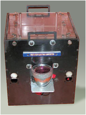
Accordingly, it is an objective of the present invention to provide a method of electrical power generation from this ever increasing human population that does not negatively impact the environment. On the other hand, human population all over the world and hence energy demand is increasing day by day linearly. In order to develop a technique to harness foot step energy, a foot step electricity generating device was developed in the Reactor Control Division, BARC. This device, if embedded in the footpath can convert foot impact energy into electrical form. If such devices are embedded in places where there is continuous human traffic such as in city malls, railway platforms, city footpaths etc., the electricity generated from these devices can be used for street lights. The device developed at the Reactor Control Division is shown in Fig. 1. The device was tested and it was demonstrated that the energy generated by this device can be stored in a 12 V lead acid battery. A 100 watt, 230 volt bulb was connected to the battery through an inverter. The device was operated by persons walking over to it. The bulb automatically lights up when the battery reaches its full voltage. The bulb remained lighted till the battery was exhausted. However, if there is continuous movement of pedestrians over the device, the bulb can be kept lighted continuously.
Principle
This setup works on the principle of converting the linear motion due to pressure of foot steps into rotary motion. This rotary motion is utilized to rotate a power generating device to generate power which is stored using dry battery. This rotation is depend upon weight of person walking over the platform and the tension of the spring used. Depending upon the power generator used, the power output can be increased.
CONSTRUCTION
- A flooring system made up of blocks is installed that depress slightly under the force of human steps.
- As the people walk over them the flooring system depresses to a little extent which in turns depresses the mechanical setup installed beneath it.
- This mechanical setup consists of top platform and immovable bottom platform.
- Other component of this system are:-
- four primary spring
- lever assembly
- shaft fitted with two free wheel bearings
- large pulley
- smaller pulley
- power generator
- The spring is installed in four corners which provide compression in the top layer.
- Then it consist of lever assembly, two freewheel bearings fitted with shaft.
- A large pulley is attached to the shaft and a smaller pulley is connected with large pulley.
- This small pulley is coupled with dynamo which rotates when the small pulley is rotated.
WORKING
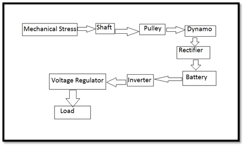
When people walk on the floor, the floor press on the mechanical setup. The setup depresses due to the spring action and pulls the lever assembly which rotates one of the freewheel bearing fitted to the shaft as shown in block diagram.
The shaft then rotates the large pulley which is connected to the smaller pulley through a V-belt. This smaller pulley acts as a reducer which provides more rotations corresponding to one rotation of the large pulley.
This smaller pulley coupled with the dynamo , a device that converts the energy of motion into electric current and power is obtained. This process depends on two factors, primary spring tension and type of generator used.
The primary spring tension is determined by calculating the average weight over a locomotive area. To get more power output, type of generator is considered as the main factor. When the pressure is applied through a foot step, ninety-five percent of the pressure applied is converted into energy in this method.
AVERAGE WEIGHT OF LOCOMOTIVE AREA
- It is the parameter of foot step electric converter (FSEC).
- For example, if the system is installed in a higher secondary school, the spring tension must be able to withstand the loads of different students, group, staffs etc.
- The average weight is in between 65 to 70 kg. So the spring tension must withstand 5 kg less and more to average weight.
- The whole weight is acting on both the spring tension and hinges of the flooring system.
- But this varies in case of a railway platform where people of different age, group moves.
- The average weight may vary up to 75kg to 85 kg.
- That’s why spring tension withstands according to place, age and weight.
Block Diagram
FLOORING SYSTEM:-
When the mechanical setup is used as it is, every single setup will compress separately and give an awkward feeling while walking over that. To prevent this, a flooring system is installed over the mechanical setup. The purpose of installing this flooring system is to provide required compression and at the same time to prevent the people to feel uncomfortable when walking over it.
As every block over the setup is connected to one another using hinge arrangement, the compression will not be felt as the weight of the person walking over that will be distributed. But the pressure required to compress the setup will be conveyed as the person’s weight acts on the particular setup only.
Depending upon the average weight over a locomotive area, the strength and number of hinges are used. For the area where average weight is more, the numbers of the hinges are increased. This along with the primary spring provides the required compression for the setup.
POWER GENERATED:-
We use two 6V AC dynamo as the power generator for this project. The main advantage this provided was the small rated speed required to produce power of 6 watts and a current of 1A in each of the dynamo.
The total current accounted for the two dynamo was 2A and this was rectified and stored in a 6W dry battery. This battery will get charged fully within 3 hours when charged using power producing platform. This time will be considerably reduced when we use number of dynamo to charge a single 6W dry battery. A single power producing platform can accommodate 4 dynamos and when the battery is charged using all the current from these 4 dynamos, time taken to charge completely reduces below 2 hours. The battery can be used to supply the requirement as from then and there or it can be ported to place of requirement. For example if this project is used in railway platform, all the batteries powered by several setups in the daytime can be used to supply the way lights across the platform during the night time.
SECONDARY SPRING:-
There is a secondary spring arrangement which consists of a spring and a break system. This arrangement is used to produce additional rotation time to the generator. When the setup is compressed continuously, this spring gets wound on the shaft slowly. The reverse rotation of the shaft under the tension of the spring is prevented by the break system and second freewheel bearing that is fitted to the shaft until the spring attains its maximum tension. By the time the spring attains its maximum tension, the break releases and the freewheel bearing rotates the shaft on the opposite side. This rotates the large pulley which in turn rotates the small pulley and the dynamo. This increases the time period of the rotations of the generator.
ADVANTAGES
- Highly efficient in more crowded places.
- This process depends on human resources which is available in plenty of amount in our country.
- Promising technology for solving power crisis to an affordable extent.
- Low cost level.
- Simple in construction.
- Pollution free.
- Reduces transmission losses.
- Wide areas of application.
APPLICATIONS
- Railway, subway stations
- Roads
- Temples
- Bus stands, Airports
- Music halls, auditoriums
- Markets
CONCLUSION
- Thus this is a great technology to provide efficient solution to power crisis.
- This will be the most acceptable means of providing power to the places that involves difficulties of transmission.
- This technology would facilitate the future creation of new urban landscapes, athletic fields , music halls, theaters, nightclubs and a large gathering space for rallies, railway stations, bus stands, subways, airports etc.